Messtechnik
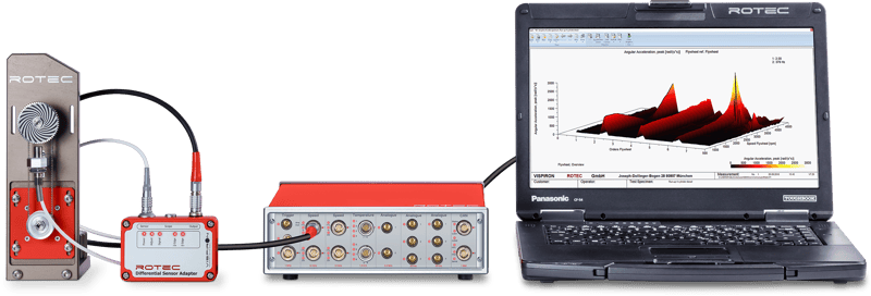
Sensoren, Signal-Conditioning, RASdelta Messsystem (DAQ) mit Messkarten für alle relevanten Anwendungsfälle in der Entwicklung und Optimierung von modernen, effizienten und zuverlässigen Antriebssträngen: Die ROTEC Messtechnik Produkte ermöglichen dem Anwender eine nahtlos integrierte Messkette von Drehzahlsensor bis DAQ mit einer aufeinander abgestimmten Messlösung.
Überzeugen Sie sich von der Leistungsfähigkeit unserer Produkte und vereinbaren Sie einen individuellen Beratungstermin.
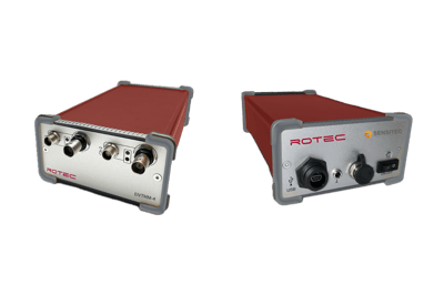
RASdelta Messsystem
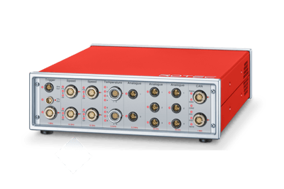
Beim RASdelta Messsystem handelt es sich um ein modulares, flexibel einsetzbares und hochpräzises Datenerfassungssystem (DAQ). Das Gerät ist als 8-Slot und als 16-Slot Variante verfügbar und kann für individuelle Messaufgaben am Prüfstand und für dynamische Messungen im Fahrzeug konfiguriert werden.
Das System bietet neben der kompakten Bauform ein Touch-Bedienfeld, über das das RASdelta auch als Datenlogger konfiguriert werden kann. Das Kaskadieren von bis zu 6 RASdelta Systemen ist über die zweite Ethernet Schnittstelle problemlos möglich.
Das Messsystem wird vom Anwender für den individuellen Anwendungsfall konfiguriert. Hierzu werden die benötigten Messkarten aus dem Katalog unten ausgewählt.

-
Click to view TriggerkarteTriggerkarte
-
Click to view DrehzahlkarteDrehzahlkarte
-
Click to view AnalogkarteAnalogkarte
-
Click to view TemperaturkarteTemperaturkarte
-
Click to view DMS-KarteDMS-Karte
-
Click to view CAN-BUS-KarteCAN-BUS-Karte
Die RASdelta Triggerkarte synchronisiert alle Messdaten zwischen den Kanälen, Erfassungsmodulen und angeschlossenen Frontends. Als Masterkarte ist sie ein integraler Bestandteil des RASdelta.
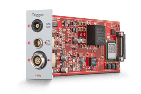
- Synchronisiert alle Messkarten, Kanäle und kaskadierten Systeme
- 1x TTL-Triggereingang mit einstellbaren Schwellenwerten
- 2x TTL-Ausgang zur Online Überwachung
- Spannungsversorgung für Elektronikeinheiten (DC 5 V und 12 V; 5 W)
Das RASdelta Speed Board erfasst präzise mehrkanalige und digitale Drehzahlmessdaten für alle Getriebe-, Steuerungs- und Nebenantriebsprüfungen. Es ist damit die Basis für die Drehschwingungsanalyse. Die Daten werden über eine magnetische, winkeläquidistante Abtastung, einen Inkrementalgeber oder einen Laser erfasst.
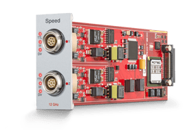
- 2-Kanal-Messkarte mit 12,3 GHz Zählertakt (Zeitauflösung = 0,081 Nanosekunden)
- Signaleingänge für Richtungs- und Referenzimpulserkennung
- Einstellbare Werte für Triggerschwelle und Flanke
- Betriebsarten: Drehzahl, Frequenz, Tastverhältnis, Ein/Aus-Verhältnis
Das RASdelta Analog Board misst analoge Größen wie Luft- und Körperschall, Beschleunigung, Temperatur, Weg oder Druck. Diese Größen können verwendet werden, um die Position einer Schallquelle zu bestimmen oder den Ventiltrieb oder den Zylinderdruck zu analysieren. Die analogen Messdaten werden durch äquidistante Abtastung erfasst.
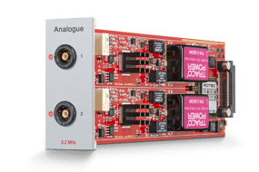
- 2 analoge Spannungseingänge, galvanisch getrennt
- AC- und DC-Kopplung, Spannungsversorgung für IEPE (ICP) Sensoren
- Einstellbare Spannungsbereiche für Eingangssignale
- 16 Bit SigmaDelta ADC
- 3,2 MHz max. Abtastrate bei einkanaliger Nutzung
- 1,6 MHz max. Abtastrate pro Kanal bei Zweikanalbetrieb
- 1,2 MHz analoge Bandbreite
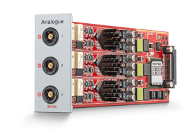
- 3 analoge Spannungseingänge, galvanisch getrennt
- AC- und DC- Kopplung, Stromversorgung für IEPE (ICP) Sensoren
- Einstellbare Spannungsbereiche für Eingangssignale
- 24 Bit SigmaDelta ADC
- 50 kHz max. Abtastrate pro Kanal
- 24 kHz analoge Bandbreite
Mit der RASdelta Temperatur-Messkarte erfassen Sie Messdaten von Widerstandsthermometern und Thermoelementen.
Gerade bei Getriebeuntersuchungen ist die Messung der Öltemperatur in Fahrzeugen unerlässlich.
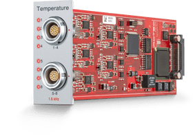
- 8-Kanal-Messkarte
- Maximale Abtastrate: 1,6 kHz pro Kanal (bei Verwendung von 4 Kanälen)
- Temperaturmessbereich: -200°C - 850°C
- Unterstützte Sensoren:
- Pt100/1000
- Thermoelement Typ J (Fe/CuNi)
- Thermoelement Typ K (NiCr/Ni)
- Thermoelement Typ T (Cu/CuNi)
Das RASdelta DMS-Karte ist ein integrierter Zweikanal-Gleichspannungsverstärker für die Signalerfassung von Dehnungsmessstreifen-basierten, piezoresistiven, magnetoresistiven oder potentiometrischen Aufnehmern. Dazu gehören Kraft-, Drehmoment-, Druck-, Weg- und Winkelsensoren oder Maßstäbe. Die Karte benötigt keine zusätzlichen Messverstärker.
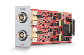
- 2-Kanal-Messkarte
- Max. Abtastrate: 50 kHz pro Kanal
- Unterstützt Vollbrücken- und Halbbrückenanwendungen
- Einstellbare Brückenversorgungsspannung: 1 V, 2,5 V, 5 V, 10 V
- Unterstützt Vierdraht- und Sechsdraht-Konfiguration
- Automatischer Nullabgleich
- Erkennung von Leitungsunterbrechungen/Burn-Out
Die CAN-BUS-Karte zeichnet CAN- und OBD-II-Variablen auf und wertet diese in Bezug auf die Drehschwingungsanalyse aus. Damit können vorhandene Größen ohne weitere Sensorapplikationen in die Messung einbezogen werden. Neben OBD II, Raw CAN und SAE J1939 Protokoll ist es möglich, FD CAN Daten direkt über den Mess-PC und separate Fremdhardware aufzuzeichnen.
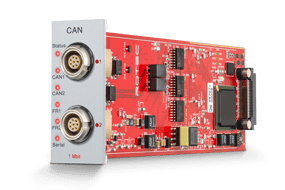
- 2-Kanal-Messkarte
- Max. Baudrate: 1 Mbit/s pro Kanal
- Einstellbare Post-Sampling-Rate
- CAN-Standard 2.0 A (11-Bit-Identifier) und 2.0 B (29-Bit-Identifier); OBDII; J1939; (CAN-FD über PC USB-Anschluss)
- Modi: aktiver/passiver Mithörer
- Einstellbarer BUS-Abschluss (120 Ohm)
-
Click to view DifferentialsensorDifferentialsensor
-
Click to view LasersensorLasersensor
-
Click to view GMR SensorGMR Sensor
Die magneto-resistiven Differentialsensoren von ROTEC dienen zum Erfassen von Drehzahlen an ferromagnetischen Zahnrädern und sind in unterschiedlichen Bauformen für die anspruchsvollsten Einbausituationen erhältlich.

TYP A
- Zweiteilige Ausführung - die Vorzugsrichtung ist nach der Montage des Sensors einstellbar
- Geeignet für den Standard-Temperaturbereich -15°C bis 100°C
- Optional mit Drehrichtungserkennung (4-fach Sensor)
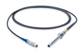
TYP B
- kurze Sensorlänge
- Standard-Temperatursensor (Temperaturbereich -15°C bis 100°C) mit abnehmbarem Anschlusskabel
- Hochtemperatursensor (Temperaturbereich -15°C bis 160°C) mit integriertem Kabel, inkl. Adapterkabel
TYP C
- Abgewinkelter 90° Sensorkopf
- Standard-Temperatursensor (Temperaturbereich -15°C bis 100°C) mit abnehmbarem Anschlusskabel
- Hochtemperatursensor (Temperaturbereich -15°C bis 160°C) mit integriertem Kabel, inkl. Adapterkabel
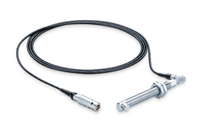
Die ROTEC Lasersensoren dienen zum Erfassen von Drehzahlen durch Abtastung eines schwarz-weiß (Zebra) Strichmusters. Es können sowohl Strichbänder als auch Strichscheiben verwendet werden. Die Strichmuster sind in verschiedenen Standards erhältlich. Die Behandlung der Stoßstelle bei Verwendung von Strichbändern ist über einen Korrekturmechanismus in der RAS Software problemlos möglich.

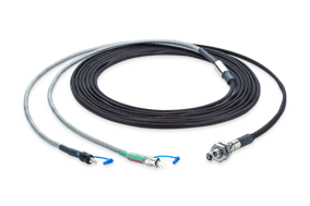
Lasersensor (SeLas 4/5)
- Abtastung des Objekts von vorne oder über einen Umlenkspiegel im 90°-Winkel möglich
- Lichtwellenleiter mit Textil- oder Metallummantelung erhältlich
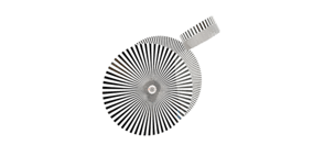
Strichmuster
- Hochwertige Strichmuster verbessern die Qualität des Drehzahlsignals
- Strichbänder und Strichscheiben erhältlich in Standarddimensionen
- Kundenspezifische Strichmuster auf Anfrage
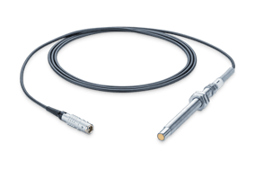
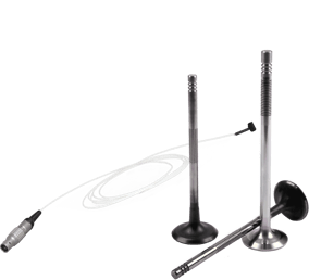
Der Sensitec Sensor GLM711AVB ist für die Verwendung mit passiven Skalen mit einem Raster von 1 mm vorgesehen. Ein Bias-Magnet für das erforderliche Magnetfeld und das Sensorlement sind in einem sehr kleinen Gehäuse kombiniert. Die Integration unterstützt eine optimale Ausrichtung zwischen Sensor und Magnet, was zur Erzeugung eines sehr hochwertigen Sensorsignals beiträgt.
In Kombination mit einer ferromagnetischen Zahnstruktur liefert der Sensor zwei um 90 Grad phasenverschobene analoge Signale (Sinus und Kosinus).
Der typische Anwendungsbereich des Sensors ist die Messung von Ventilerhebungskurven im befeuerten Motorbetrieb. Auch die Messung von Ventilrotation ist möglich.

-
Click to view Differential Sensor AdapterDifferential Sensor Adapter
-
Click to view Laser TachometerLaser Tachometer
-
Click to view Rotary Encoder AdapterRotary Encoder Adapter
-
Click to view 4-fold Sensor4-fold Sensor
-
Click to view Encoder Phase ShifterEncoder Phase Shifter
-
Click to view GMR Sensor AdapterGMR Sensor Adapter
-
Click to view Ventiltrieb MessmodulVentiltrieb Messmodul
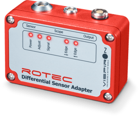
Der Differential Sensor Adapter (DSA) wandelt das sinusförmige Signal des ROTEC Magnetsensors in eine Impulsfolge von Nadelimpulsen mit TTL-Pegel, die von der RASdelta Drehzahlmesskarte verarbeitet wird.
Eine LED Anzeige erleichtert dem Anwender die optimale Einrichtung des Differentialsensors gegenüber der Verzahnung, um eine bestmögliche Signalqualität zu erreichen.

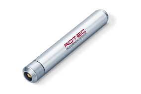
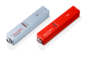
Der Inline TTL Digitizer (Inline-DSA) ist die kompakte Ausführung des ROTEC Differential Sensor Adapters (DSA) und eignet sich besonders für den mobilen Einsatz. Die Elektronik wandelt das sinusförmige Signal des ROTEC Magnetsensors in eine TTL-Impulsfolge, die von der RASdelta Drehzahlmesskarte verarbeitet wird.

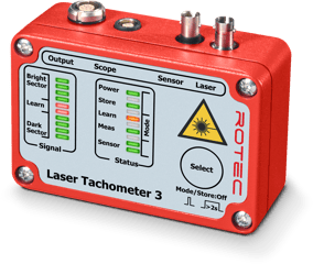
Das ROTEC Laser Tachometer 3 (ELLAS3) dient zur optischen Messung der Drehzahl. Die Elektronik erzeugt ein leistungsgeregeltes Laserlicht, das vom ROTEC Lasersensor auf ein am Messobjekt angebrachtes schwarz-weiß Strichmuster übertragen wird. Die Hell-Dunkel-Übergänge des Messobjekts werden im Reflexverfahren abgetastet. Daraus resultiert eine Impulsfolge mit TTL-Pegel, die von der RASdelta Drehzahlmesskarte verarbeitet wird.

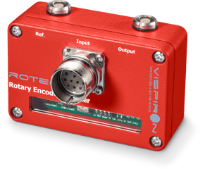
Der Rotary Encoder Adapter (ELDGADP2) dient zur Erfassung von TTL- oder SIN/COS-Drehgebersignalen.
Aus den Signalen des Inkrementalgebers erzeugt die Elektronik eine digitale Impulsfolge mit TTL-Pegel. Der Rotary Encoder Adapter erfasst die Gebersignale vorwärts und rückwärts und leitet daraus Richtungsinformationen ab. Die Signale für die Drehzahl und Drehrichtung sowie der Referenzimpuls werden von der RASdelta Drehzahlmesskarte erfasst und verarbeitet.
Der Referenzimpuls lässt sich zudem an einer separaten Buchse abgreifen und als Starttrigger für Messungen verwenden.

Der Inline DGADP ist die kompakte Ausführung des ROTEC Rotary Encoder Adapters und eignet sich besonders für den mobilen Einsatz. Zudem ist der Adapter in zwei Varianten erhältlich: für TTL- und für HTL- Inkrementaldrehgeber.
Aus den Signalen des Inkrementalgebers erzeugt die Elektronik eine digitale Impulsfolge mit TTL-Pegel, die als Messsignal dient. Der Inline DGADP erfasst die Gebersignale vorwärts und rückwärts und leitet daraus Richtungsinformationen ab.

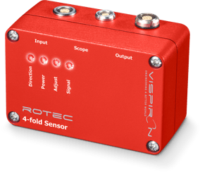
Die Elektronik zur Drehrichtungserkennung (EL4FP) wandelt das sinusförmige Signal des ROTEC Magnetsensors in eine Impulsfolge von Nadelimpulsen mit TTL-Pegel. Bei Verwendung des ROTEC 4-fach Magnetsensors kann die Richtungsinformation abgeleitet und an die RASdelta Drehzahlkarte übergeben werden.

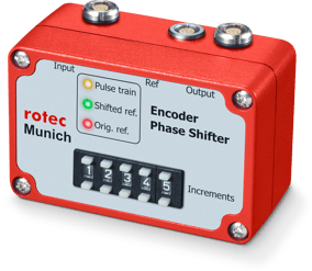
Der ROTEC Phase Shifter wird in Verbindung mit dem ROTEC Rotary Encoder Adapter eingesetzt. Der Phase Shifter verzögert das Referenzsignal eines Drehgebers um eine einstellbare Anzahl von Drehzahlimpulsen (=Inkrementen). Die originale Referenzmarke wird unterdrückt und durch eine synthetisch erzeugte Marke ersetzt. Dieser synthetische Referenzpuls kann separat abgegriffen und als Start-Trigger für Messungen verwendet werden.

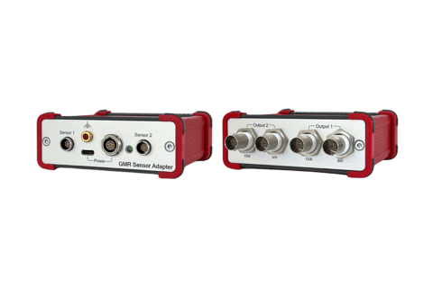
Der GMR Sensor Adapter (ELGMR) eignet sich für Ventilhubmessungen mit dem GLM711AVB GMR Sensor. Die Elektronik dient dazu, die erfassten Rohsignale zu verstärken und ein rauschfreies Signal sowie eine ausreichende Bandbreite zu gewährleisten.
Die verstärkten Sensor-Signale werden über separate Sinus- und Cosinus-Ausgänge ausgegeben und können mit der 3,2 MHz RASdelta Analogmesskarte aufgezeichnet werden.

Das Ventiltrieb Messmodul (ELVTMM, ehemals Sensitec SPP3001) dient als Auswerteeinheit für Messungen am Ventiltrieb. Die Elektronik konditioniert das Sensorsignal und errechnet einen Online Ventilhub mit einer Genauigkeit von +/- 10 μm, der am BNC Stecker als Ausgangsspannung zwischen 0-10 V bereitgestellt wird. Das Modul ist in 2- und 4- Kanal Variante verfügbar.
Zur weiteren Verarbeitung des Ventilhubsignals bietet das ROTEC RAS Software Paket "Ventiltriebsanalyse" tiefgehende dynamische Analysemöglichkeiten.