-
Click to view SteuertriebSteuertrieb
-
Click to view NebenaggregateNebenaggregate
-
Click to view Kupplung/DämpferKupplung/Dämpfer
-
Click to view GetriebeGetriebe
-
Click to view NVH (Noise, Vibration, Harshness)NVH (Noise, Vibration, Harshness)
-
Click to view VentildynamikVentildynamik
Problem: Erhöhter Schadstoffausstoß, geringe Lebensdauer der Bauteile
Ziel: Präzise Auslegung des Steuertriebs
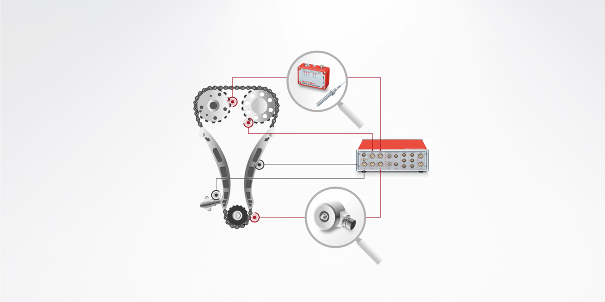
Der Schwerpunkt der Automobilentwicklung bei Verbrennungsmotoren liegt auf der Reduzierung des Kraftstoffverbrauchs und der Schadstoffemissionen. Steuertriebe und Ventiltriebe bestimmen die Effizienz von Verbrennungsprozessen. Sie dienen der Synchronisation von Kurbel- und Nockenwelle zur Steuerung des Öffnungs- und Schließverhaltens der Ventile. Ein dynamisch nicht optimal abgestimmter Steuertrieb reduziert die Lebensdauer der Bauteile und erhöht den Schadstoffausstoß.
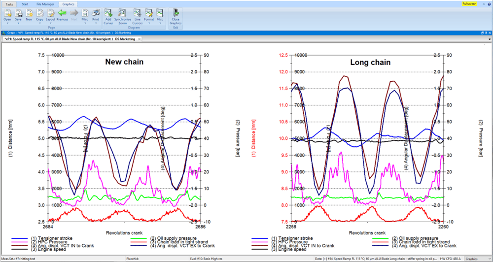
Zur Untersuchung der Steuerzeiten und Ventiltriebe wird eine mehrkanalige Drehzahlmessung an den Nockenwellen und mittels eines Drehgebers eine Messung der Position und Drehzahl an der Kurbelwelle durchgeführt. In Kombination mit analogen Messgrößen ergeben die Messungen ein umfassendes Gesamtbild über das dynamische Verhalten des Steuertriebs bei unterschiedlichen Lastzuständen. Analoge Messgrößen können z.B. der Öldruck des Kettenspanners, die Kettenkraft und Beschleunigungen an den Kettenführungen sein.
Die aufgezeichneten Messwerte werden im Zeit- und Spektralbereich ausgewertet.
Außerdem unterstützt Sie ROTEC ENGINEERING mit fachlichem Ingenieurswissen bei Problemstellungen rund um Schwingungsanalysen an Motoren, Getrieben und Antriebssträngen. Mit unserem Know-how leisten wir einen wertvollen Beitrag zu Ihrem Produkt in den Bereichen Steuertriebvalidierung, Ventiltrieboptimierung, Kupplungsauslegung, Übertragungsfehler (TE), Getriebe- und Ölhaushaltsoptimierung, Antriebsstrangvermessung und -optimierung, Strom- und Spannungsanalyse sowie die Applikation von Messtechnik.
Analysen im Zeitbereich
- Spannerkräfte
- Schwing- und Verdrehwinkelanalyse in Phase
- Öldruckverhältnisse bei hydraulischem Spanner
- Schließverhalten des Rückschlagventils
- Erkennung des Kontollverlustes
- Detektieren des Ketten- bzw. Riemenschlagens
- Detektieren der Startgeräusche
Analysen im Spektralbereich
- Klassische Ordnung- und Frequenzanalysen
- Überprüfung des Resonanzverhaltens des Triebes
- Analyse der Anregungen
- Erstellung von Hüllkurven über Drehzahl
- Optimierung der Phasenlage der Anregungen (Hochdruckpumpen)
- Analyse der Zugmittelgeräusche
Problem: Schlupf, Riemenschwingungen, Verschleiß der Riementriebkomponenten
Ziel: Präzise Auslegung der Nebenaggregate
Nebenantriebe wie die Servolenkungspumpe oder der Klimakompressor, der die Temperatur im Fahrzeug regelt, sorgen für einen hohen Fahrkomfort. Um Schäden zu vermeiden, muss bei den Nebenantrieben stets auf die richtige Riemenspannung geachtet werden. Eine zu geringe Spannung führt zu Schlupf und Riemenschwingungen und damit zu einem vorzeitigen Verschleiß der Riementriebkomponenten.
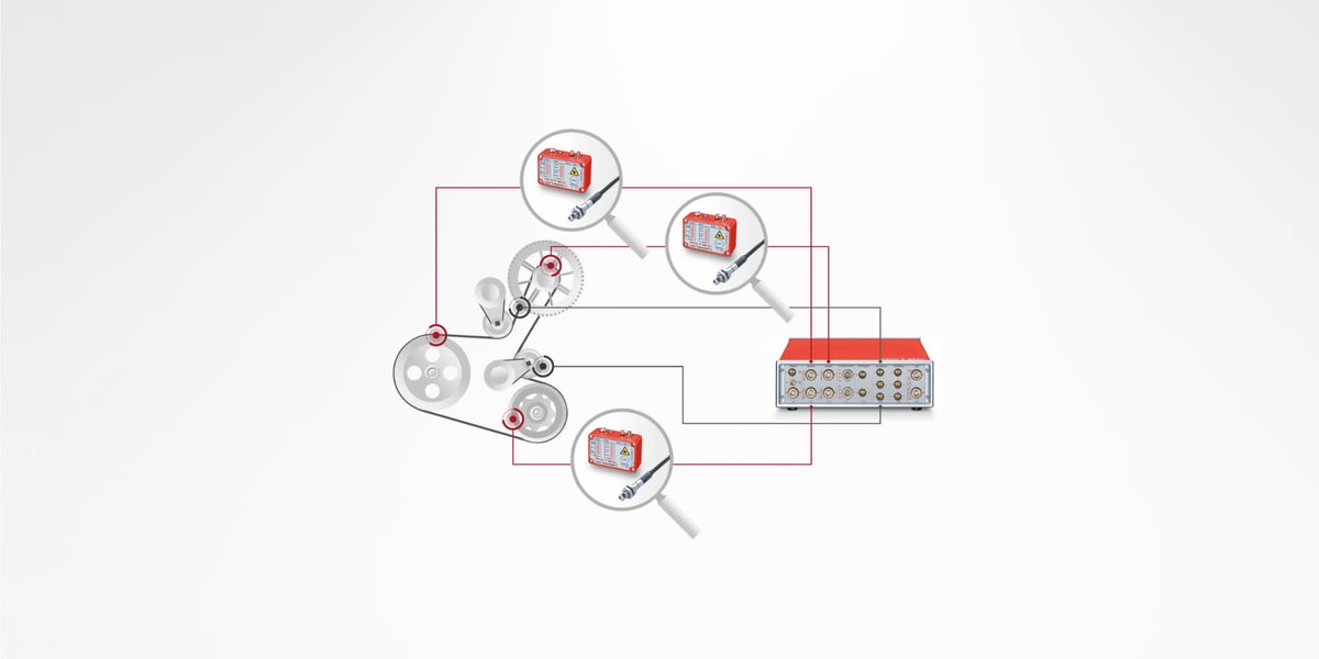
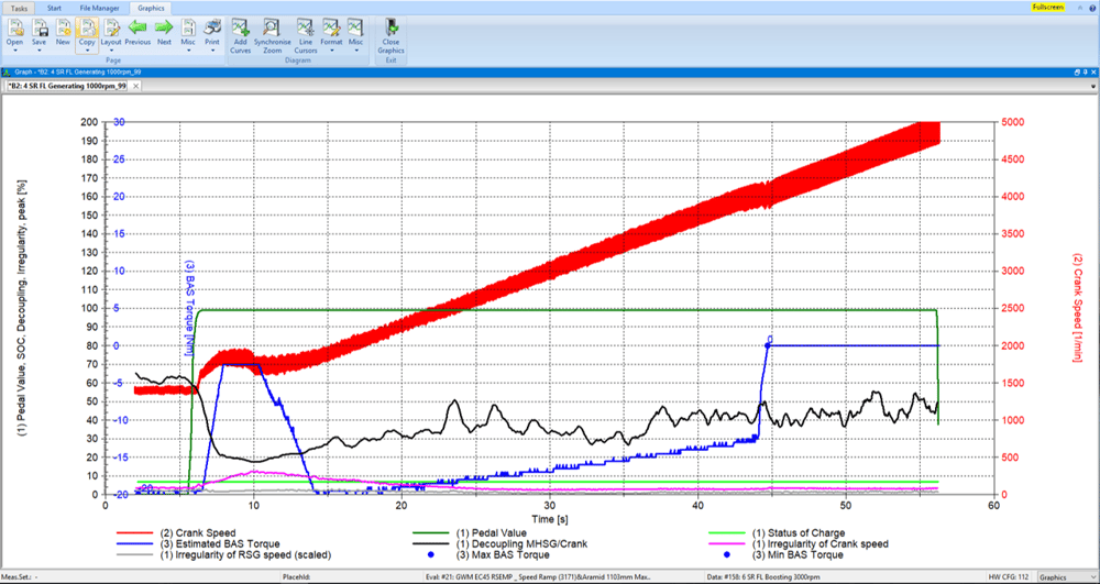
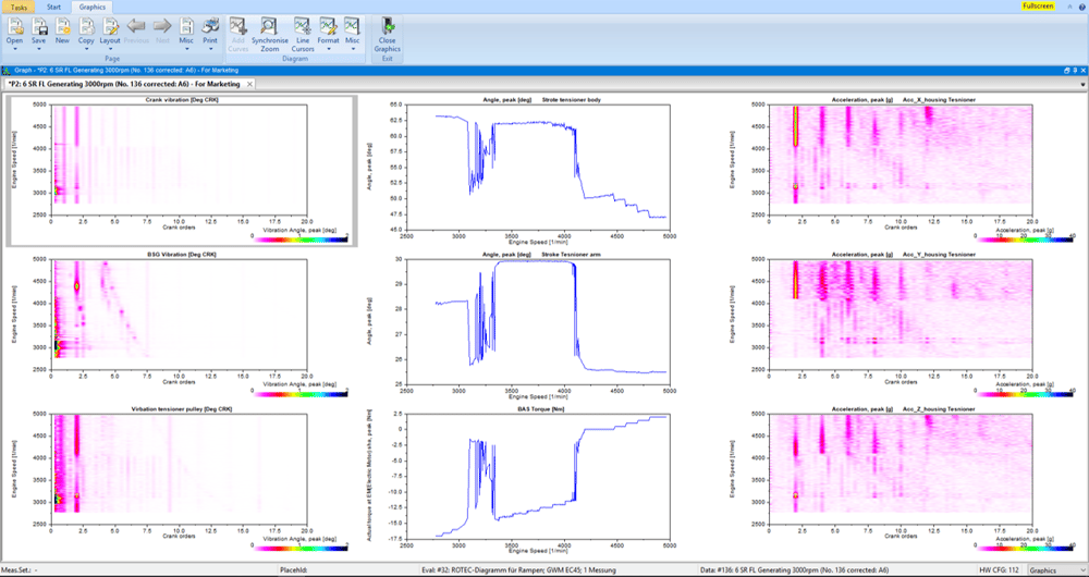
Die Funktionsprüfungen an Hilfsantrieben (FEAD) und Riemen-Starter-Generator-Antrieben (BAS) umfassen die Messung und Bewertung des Schlupfes und des dynamischen Verhaltens des gesamten Riementriebsystems.
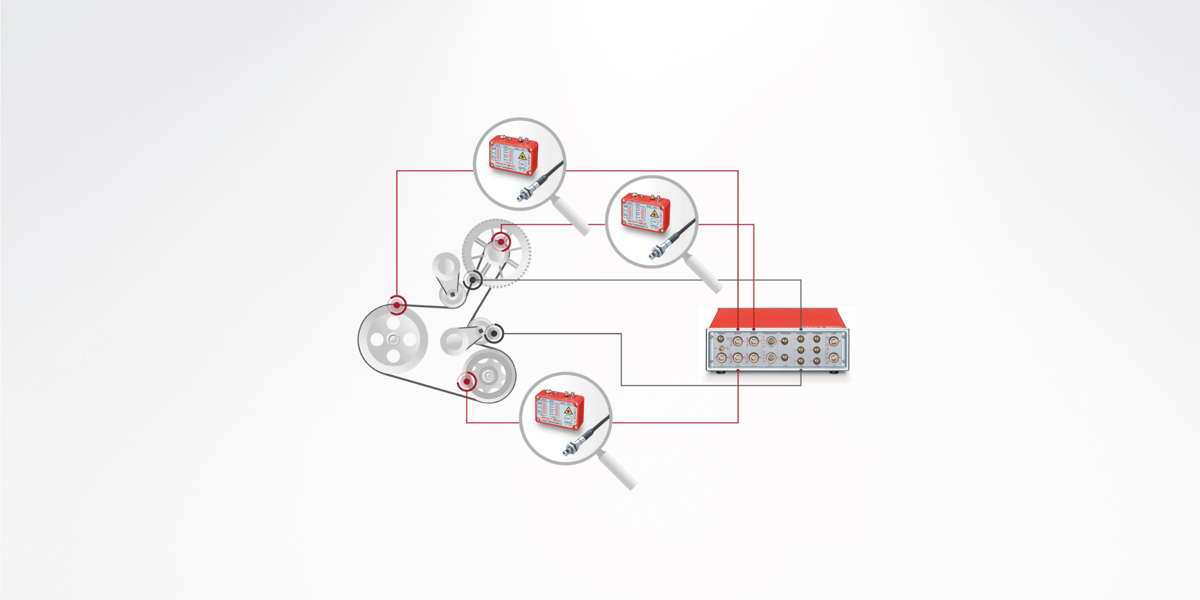
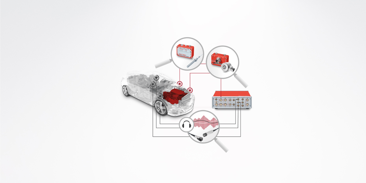
Im Bild sind neben der hochauflösenden Messung der Drehwinkelstellung der Kurbelwelle und aller anderen Riemenscheiben die Riemenkräfte, Spannerbewegungen und Riemenschwingungen wichtige Messgrößen. Darüber hinaus haben der Betriebszustand des Motors und die Lastzustände der Nebenaggregate sowie das aktuelle Drehmoment des BAS-Generators einen wesentlichen Einfluss auf das Antriebsverhalten. Die Auswertung erfolgt im Zeit- und Spektralbereich.
Bei Hybridantrieben spielt der Ladezustand der Batterie eine wesentliche Rolle. Hier stehen die meisten Größen mit ausreichender Auflösung auf dem CAN-BUS zur Verfügung und können mit der ROTEC-CAN-BUS-Karte aufgezeichnet werden.
In BAS-Systemen stellen die Start- und Stoppvorgänge des Motors sowie die Umschaltung des Startergenerators zwischen Motor- und Generatorbetrieb (Rekuperation) einen der schwierigsten dynamischen Zustände dar, weshalb eine Sensorik mit Drehrichtungserkennung erforderlich ist, um die richtigen Drehzahlverhältnisse zu erfassen. ROTEC bietet für diese Aufgabe entsprechende Sensorlösungen wie Geberanpassungsmodule oder Vierfachsensoren.
Die aufgezeichneten Messwerte werden im Zeit- und Spektralbereich ausgewertet.
Außerdem unterstützt Sie ROTEC ENGINEERING mit fachlichem Ingenieurswissen bei Problemstellungen rund um Schwingungsanalysen an Motoren, Getrieben und Antriebssträngen. Mit unserem Know-how leisten wir einen wertvollen Beitrag zu Ihrem Produkt in den Bereichen Steuertriebvalidierung, Ventiltrieboptimierung, Kupplungsauslegung, Übertragungsfehler (TE), Getriebe- und Ölhaushaltsoptimierung, Antriebsstrangvermessung und -optimierung, Strom- und Spannungsanalyse sowie die Applikation von Messtechnik.
Analysen im Zeitbereich
- Riemenbelastungen
- Lagerkräfte
- Spanner Vorspann- und Dämpfungskräfte
- Kraftvektorberechnung abhängig von der Spannerposition
- Schlupfverhalten im Gesamttrieb
- Start und Stoppverhalten
- Drehzahlgradient- und Spitzenmomentauswertungen
Analysen im Spektralbereich
- Resonanzverhalten des Spanners
- Resonanzverhalten des Gesamtriebes
- Automatische Erstellung von Ergebnistabellen
- Dekopplungsverhalten
Problem: Kurbelwellentorsion, Kupplungsschlupf
Ziel: Optimale Auslegung Kupplung
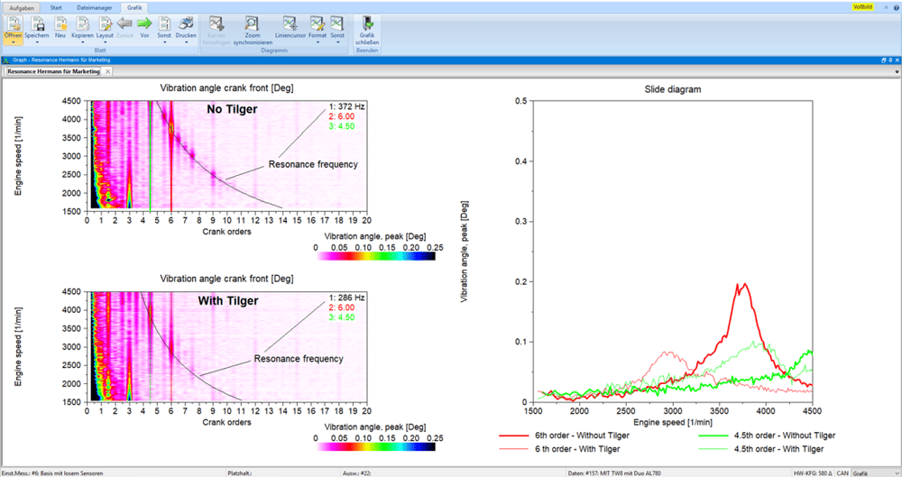
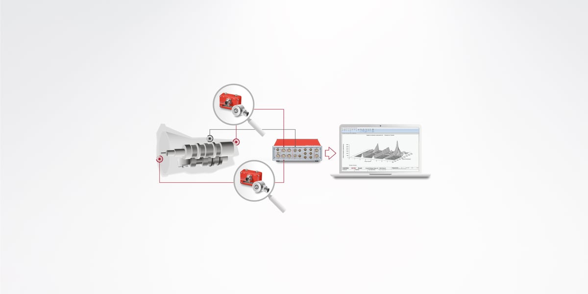
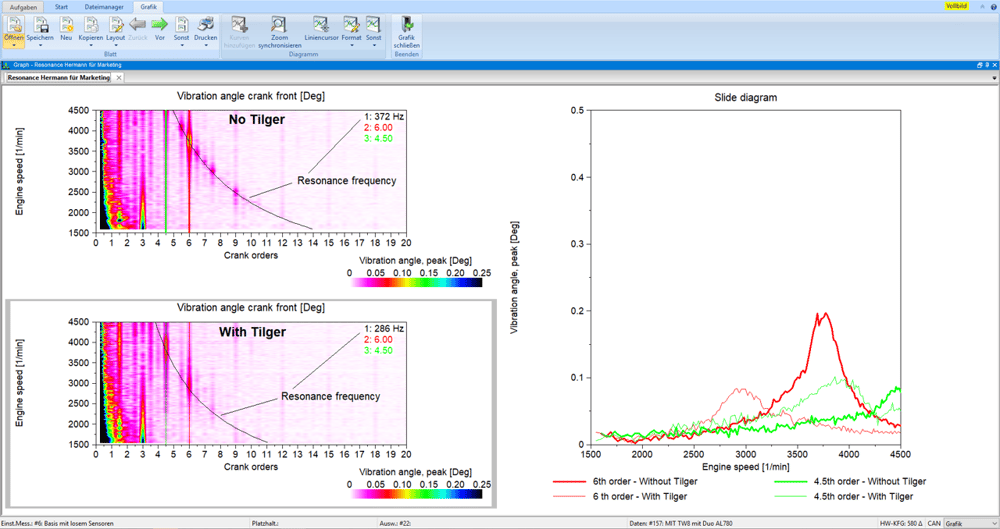
Moderne Motoren werden immer kompakter, leistungsfähiger und sparsamer. Dieser Effekt – auch Downsizing genannt – führt zu einer Erhöhung der Verbrennungsdrücke und zu einer Verringerung der Massenträgheit der Kurbelwelle in Verbrennungsmotoren. Da dadurch die Drehungleichförmigkeiten deutlich zunehmen, stehen die Hersteller von Kupplungen und Schwingungsdämpfern vor einer neuen Herausforderung. Die Messung und Bewertung der Kurbelwellentorsion, des Kupplungsschlupfes und des Verhaltens eines Schwingungsdämpfers ist daher unerlässlich, um die Funktionssicherheit und Lebensdauer der einzelnen Komponenten zu gewährleisten.
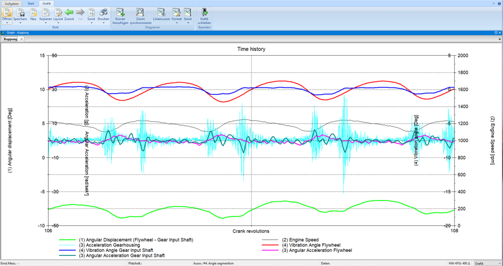
Bei der in Abbildung dargestellten Kupplungsmessung erfolgt die Drehzahlmessung mittels eines Magnetsensors am Starterzahnkranz und an der Getriebeeingangswelle. Hauptauswertungen sind der Verdrehwinkel zwischen Motor- (Eingangs-) und Getriebeseite, Schlupf, Ordnungsanalyse, insbesondere Winkelbeschleunigungen im Getriebe (Getrieberasseln).
Im ROTEC-Produktportfolio finden Sie eine Vielzahl von unterschiedlichen Drehzahlsensoren (Laser und magnetoresistiv), die für die jeweilige Einbausituation, die Umgebungsbedingungen und die optimale Signalauflösung geeignet sind. Um den Verdrehwinkel zwischen zwei Drehzahlsignalen mit hoher Auflösung messen zu können, bietet ROTEC Drehzahlmesskarten mit 12,3 GHz an. Gleichzeitig können auch andere analoge Signale mit (max. 24 Bit und 3,2 MHz) aufgezeichnet, und so ein Zusammenhang zwischen Drehschwingungen und z.B. Rauschen analysiert werden. Die aufgezeichneten Messwerte werden im Zeit- und Spektralbereich ausgewertet.
Die erfassten Messwerte werden im Zeit- sowie Spektralbereich ausgewertet.
Außerdem unterstützt Sie ROTEC ENGINEERING mit fachlichem Ingenieurswissen bei Problemstellungen rund um Schwingungsanalysen an Motoren, Getrieben und Antriebssträngen. Mit unserem Know-how leisten wir einen wertvollen Beitrag zu Ihrem Produkt in den Bereichen Steuertriebvalidierung, Ventiltrieboptimierung, Kupplungsauslegung, Übertragungsfehler (TE), Getriebe- und Ölhaushaltsoptimierung, Antriebsstrangvermessung und -optimierung, Strom- und Spannungsanalyse sowie die Applikation von Messtechnik.
Analysen im Zeitbereich
- Analyse der statischen und dynamische Verformungen, der Winkelbeschleunigungen (Gerieberasseln) und des Verdrehwinkels (Kupplungsschlagen)
- Start- und Stoppverhalten
- Schwungradtaumeln
Analysen im Spektralbereich
- Analyse der dynamischen Anregungen
- Überprüfung des Entkopplungsverhaltens der Kupplung
- Resonanzverhalten des Gesamtsystems
- Änderung der Eigenfrequenzen der Umgebungsbedingung
- Dynamische Spitzenbelastungen
Problem: Getriebegeräusche, Übertragungsfehler (TE, Transmission Error)
Ziel: Zuverlässige Auslegung des Getriebes, Geräuschreduzierung
Störende Getriebegeräusche, Vibrationen und Rauigkeiten (NVH, Noise Vibration Harshness) mindern den Fahrkomfort massiv – insbesondere bei Fahrzeugen mit geräuscharmen E-Motoren. Mit einer zuverlässigen Auslegung des Getriebes lassen sich Geräusche reduzieren. Dafür bedarf es der Messung und Beurteilung des Übertragungsfehlers.
Getriebegeräusche
Getriebeheulen wird hauptsächlich durch das Zahnprofil und Zahnschwingungen verursacht. Im Spektrum des Übertragungsfehlers und des Körper- oder Luftschalls zeigen sich die Zahneingriffsfrequenzen mit ihren Oberwellen (Harmonischen) und Modulationsseitenbändern (hervorgerufen durch die Rotationsharmonischen; z.B. Rundlauffehler).
Getriebeheulen kann bei hoher und niedriger Last auftreten, Getrieberasseln nur bei sehr niedriger bzw. keiner Last (z.B. Leerlauf bei Verbrennungsmotor). Dann führt die vom Motor stammende Drehzahlschwankung (nicht kontinuierliche Verbrennung) dazu, dass die unbelasteten Zahnflanken der Zahnräder abheben. Das Zahnspiel wird mit jeder Beschleunigung und Verzögerung der Antriebswelle durchlaufen (mehrfach pro Umdrehung), wobei die Zähne der beiden Räder heftig gegeneinanderschlagen.
Weitere Ursachen für Getriebegeräusche können falsches Getriebeöl oder Lufteinschlüsse im Öl sein.
Übertragungsfehler (TE)
Wesentliche Ursache für Getriebegeräusche sind Übertragungsfehler (TE), die durch statische und elastische Verformung unter Last, ungewollte Fertigungsabweichungen und dynamische Effekte verursacht werden. Der Übertragungsfehler ist der Unterschied zwischen der tatsächlichen Position des Abtriebsrades und der Position, die es einnehmen würde, wenn der Zahnradsatz die Drehbewegung des Antriebsrades absolut fehlerfrei übertragen würde.
Neben Getriebegeräuschen kann der Übertragungsfehler Verschleiß, geringere Effizienz im Antriebsstrang oder direkte Störungen verursachen (mehr über Windkraftgetriebe / Wälzkörpergetriebe).
Messungen an Getrieben
Um den Übertragungsfehler zu ermitteln, werden die Drehzahlen und Winkelpositionen mit Hilfe von hochauflösenden Drehgebern an der Ein- und Ausgangswelle gemessen. Aus den gewonnenen Messdaten wird der Übertragungsfehler berechnet. Die Auswertung erfolgt im Zeit- und Ordnungsbereich.
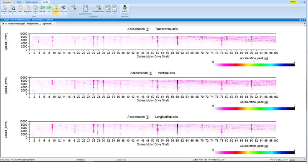
Zeitgleich werden Körperschallsignale mit einem Beschleunigungsaufnehmer aufgezeichnet. Die gemeinsame Zeitbasis aller Messkanäle ermöglicht eine Korrelation zwischen Übertragungsfehler und Schallsignalen.
ROTEC ENGINEERING
Benötigen Sie Unterstützung bei der Schwingungsanalyse an Motoren, Getrieben und Antriebssträngen? Unsere Ingenieure beraten Sie mit umfangreichem Fachwissen bei
- der Validierung des Steuertriebs
- der Optimierung des Ventiltriebs
- der Auslegung der Kupplung
- bei Übertragungsfehlern (Transmission Errors)
- bei der Optimierung von Getriebe- und Ölhaushalt
- der Vermessung und Optimierung des Antriebsstrangs
- der Strom- und Spannungsanalyse sowie
- der Applikation von Messtechnik.
Analysen im Zeitbereich
- Dynamischer Verdrehwinkel in Getriebekomponenten
- Analyse der Wellentorsionen
- Schlagartige Belastungen beim Lastwechsel
- Analyse der Steifigkeiten im Antrieb
Analysen im Spektralbereich
- Analyse der dynamischen Anregungen
- Überprüfung der Schwingungsdämpfer und Kupplungssysteme
- Resonanzverhalten des Gesamtsystems
- Änderung der Eigenfrequenzen über Umgebungsbedingung
- Dynamische Spitzenbelastungen
Analyse des akustischen Verhaltens
- Identifizierung von Geräuschquellen
- Erkennung von Bauteilresonanzen
- Spezialisierte Softwarelösung für Getriebetests
Problem: Hör- und spürbare Schwingungen
Ziel: Erhöhung des Fahrkomforts
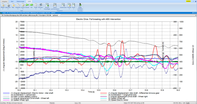
Das Geräusch- und Schwingungsverhalten (NVH = Noise, Vibration, Harshness) von Fahrzeugen rückt zunehmend hinsichtlich des Fahrkomforts in den Fokus der Automobilentwicklung. Gemeint sind damit alle hör- und spürbaren Schwingungen, die von Fahrwerk, Antriebsstrang und Rädern kommen und den Komfort beeinflussen. Batteriebetriebene E-Antriebe stellen hier eine besonders große Herausforderung dar, da kein Verbrennungsmotor die Antriebsgeräusche überdeckt und diese eher als Körper- oder Luftschall wahrgenommen werden können. Als Ursache für die Antriebsgeräusche können mehrere Effekte genannt werden. So können antriebsseitige Erregungen auftreten, die durch den Elektromotor, das Getriebe oder durch die Antriebswellen verursacht werden. Bestimmte Bauteilgruppen können auf diese Körperschallanregungen mit Eigenschwingungen reagieren und das NVH-Verhalten zusätzlich verschlechtern.
Zur Messung und Bewertung der Schwingungen werden die Drehzahlen an den drehschwingungsanregenden Bauteilen erfasst. Gleichzeitig werden Körperschallsignale mit einem Beschleunigungsaufnehmer und Mikrofonen aufgezeichnet und anschließend gemeinsam in den Ordnungs- und Frequenzbereichen ausgewertet. Für NVH-Untersuchungen bietet ROTEC hochauflösende analoge Messkarten mit ICP-Eingängen und speziellen NVH-Features in der Analysesoftware an.
Die aufgenommenen Messwerte werden im Zeit- und Spektralbereich ausgewertet. Gleichzeitig wird das akustische Verhalten analysiert.
Außerdem unterstützt Sie ROTEC ENGINEERING mit fachlichem Ingenieurswissen bei Problemstellungen rund um Schwingungsanalysen an Motoren, Getrieben und Antriebssträngen. Mit unserem Know-how leisten wir einen wertvollen Beitrag zu Ihrem Produkt in den Bereichen Steuertriebvalidierung, Ventiltrieboptimierung, Kupplungsauslegung, Übertragungsfehler (TE), Getriebe- und Ölhaushaltsoptimierung, Antriebsstrangvermessung und -optimierung, Strom- und Spannungsanalyse sowie die Applikation von Messtechnik.
Analysen im Zeitbereich
- Analyse der Verläufe der Körperschallsignale im Zeitbereich
- Korrelation zwischen dynamischen Bauteilbewegungen und Geräuscheffekten
- Ursachenforschung von Getrieberasseln oder ähnlichen Problemen

Analysen im Spektralbereich
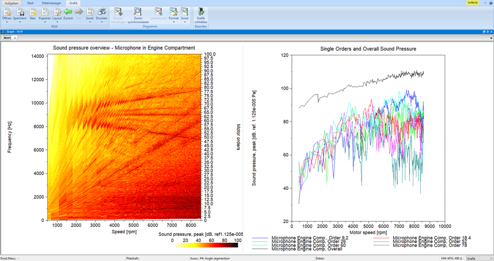
- Visualisierung der Zusammensetzung einer Geräuschkulisse
- Analyse der Einzelordnungen und des Gesamgeräuschpegels
- Analyse der Auffälligkeit und Dominanz eines Geräuschanteils
- Detektieren von Resonanzen
- Vergleich des Geräuschbildes an unterschiedlichen Orten
- Überprüfung der Effektivität von Schallisolierungen
Problem: Erhöhter Schadstoffausstoß
Ziel: Effizienter und leistungsstarker Verbrennungsmotor
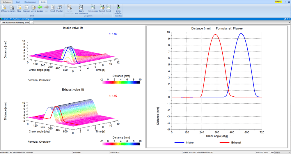
Die Entwicklung effizienter und leistungsstarker Verbrennungsmotoren ist eines der Hauptziele der Automobilentwicklung. In diesem Zusammenhang ist die Ventilsteuerung ein entscheidendes Element für die Optimierung der Thermodynamik und damit für die Effizienz von Verbrennungsmotoren.
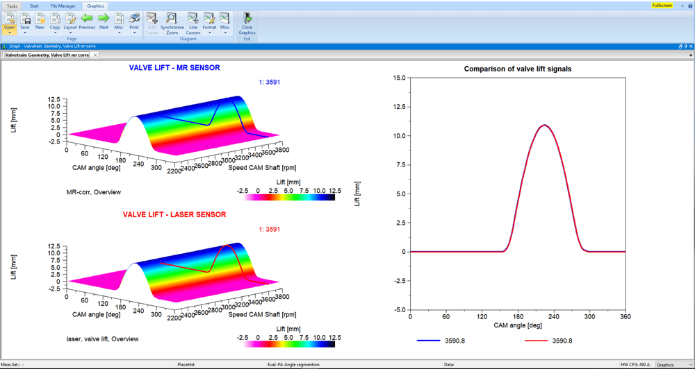
Die Analyse der Ventilsteuerung erfolgt auf Basis der gemessenen, analogen Größen Ventilhub bzw. Ventilgeschwindigkeit in Abhängigkeit von der Nockenwellenstellung. Dabei steht insbesondere das dynamische Öffnungs- und Schließverhalten des Ventils (z.B. Schließgeschwindigkeit) in Abhängigkeit von der Motordrehzahl im Vordergrund.
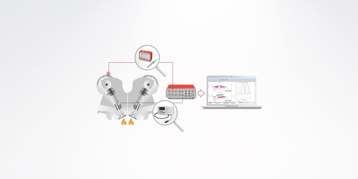
Messungen am geschleppten Zylinderkopf und am befeuerten Motor
Um das Öffnungs- und Schließverhalten zuverlässig beurteilen zu können, sind Messungen und Berechnungen der drei Messgrößen Ventilhub, Ventilgeschwindigkeit und Ventilbeschleunigung notwendig. Dazu können zwei unterschiedliche Messverfahren eingesetzt werden: die Messung am motorisierten Zylinderkopf mit einem Laservibrometer und im befeuerten Betrieb mit magnetoresistiver (MR) Sensortechnik von Sensitec. Der gemessene variable Ventilhub kann sowohl am motorisierten Zylinderkopf als auch im befeuerten Betrieb mit MR-Sensoren ermittelt werden. Dazu werden die Drehzahlsignale und Winkelpositionen am Nockenwellenantriebssystem erfasst. Daraus lässt sich in einem ersten Schritt das Drehschwingungsverhalten der Nockenwellen ableiten. Die gemessenen Daten von Drehzahlen und Ventilhub können dann im Softwaremodul Ventiltrieb ausgewertet werden. So können Größen wie Ventilgeschwindigkeit und -beschleunigung, Öffnungs- und Schließverhalten, Hubverlust, Resonanz und Spannungsverhalten automatisch ausgewertet und grafisch dargestellt werden.
Vorteile Ventiltriebsuntersuchungen am befeuerten Motor
Die Messungen am befeuerten Motor haben Vorteile gegenüber denen am geschleppten Zylinderkopf. Zum Beispiel können Sie am befeuerten Motor auch die Effekte der Gaskräfte unter realem Drehschwingungs- und Wärmeausdehnungsverhalten der Nockenwellen bzw. des Zylinderkopfes untersuchen. Diese Effekte gewinnen mit zunehmenden Lade- und Abgasgegendrücken (Partikelfilter) immer mehr an Bedeutung.
Ein weiterer Vorteil ist, dass die Kosten für den Aufbau eines teilweise sehr komplexen Versuchsteilträgers eingespart werden können.
Softwaremodul für automatisiertes Auswerten der dynamischen Parameter
Die händische Auswertung von dynamischen Parametern, wie z.B. der Ventilaufsetzgeschwindigkeit oder der Zeitpunkt des dynamischen Öffnens und Schließens, ist bei einer Vielzahl unterschiedlicher Betriebspunkte sehr mühselig und nimmt viel von Ihrer Arbeitszeit in Anspruch.
Das Softwaremodul „Ventiltrieb“ wurde mit dem Ziel entwickelt diese Auswertungen automatisiert durchzuführen. Damit kann nicht nur die Auswertezeit, sondern auch die Größe der Versuchsmatrix und dem entsprechend die Nutzungszeit des Prüfstands reduziert werden. Anstatt Messungen bei konstanten, diskreten Drehzahlen zu fahren, können Sie nun Drehzahlrampen durchführen.
Unter anderem lassen sich mit dem Softwaremodul folgende Parameter auswerten: Winkelposition des dynamischen Öffnens und Schließens, Aufsetzgeschwindigkeit, Hubverlust, Abheben, Ventilprellen, mechanische Belastung der Komponenten (Flächenpressung beim Tassentrieb), Hubfläche und Ventilüberschneidung.
Die Software wertet Verläufe mehrerer Signale aus (Hub, Geschwindigkeit und Beschleunigung) und stellt diese automatisch für jeden Zyklus mit den entsprechenden Ergebnisparametern vergleichbar dar. Bei einigen Analysen sind weitere, für den spezialisierten Nutzer vorgefertigte Auswertemethoden hinterlegt (z. B. Aufsetzgeschwindigkeit).
Zusätzlich zur Vielzahl an Analysemöglichkeiten können Sie Zyklen mit Signalfehler automatisiert erfassen und aus den Auswertungen entfernen.
Die Applikation der Messtechnik wie auch Messungen vor Ort, Analyse und Bewertung können komplett von ROTEC ENGINEERING bereitgestellt und durchgeführt werden.
ROTEC ENGINEERING führt Untersuchungen an elektrischen wie auch an hydraulischen Nockenwellenverstellern durch. Somit werden Wechselwirkungen zwischen Ventilbetätigung und Steuerzeiten erfasst oder das Funktionsverhalten der Nockenwellenversteller explizit analysiert.
- Messung von Ventilhub und Ventilgeschwindigkeit mit Laservibrometer
- Nockenwellenpositionsmessung mit Drehwinkelgeber
- Klassische Messmethode mit hochpräzisen Messsignalen
Messungen am befeuerten Motor
- Ventilhubmessung mit präparierter Ventilschaft und MR-Sensorik
- Abweichung zum Laservibrometer < 20 µm
- Spezielle Softwarelösung für Berechnung der Hubsignale aus den Sensorsignalen (SIN, COS)